Contents
- Introduction
- Digital circuits and logic gates
- Quantum circuits and logic gates
- The question
- The problem
- Simplification
- Implicit computation
- The “placebo effect”
Introduction
This blog post describes an interesting experience of solving a mathematical problem that occurred when I was completing a quantum computing course from the MIT Open Learning Library. My goal in writing the post is not to provide a formal demonstration of the placebo effect but to reflect on the learning process and explore the curious ways in which solutions can emerge. I have striven neither to be scientifically nor mathematically rigorous and make no apology for potentially hand-wavy or dubious definitions, explanations, analysis and analogies.
The problem I was tackling involved constructing a quantum circuit, which required the use of quantum gates. To explain what happened, I will need to tell you about quantum circuits and gates. However, I will do my best to keep the technical details simple to follow. If you already know about quantum computing, feel free to skip ahead.
Digital circuits and logic gates
In the world of classical computing, everything revolves around digital circuits. These circuits are like the building blocks of our digital devices, such as smartphones and computers. They use units called “bits” to represent information. A bit can be in one of two states: 0 or 1, which can be thought of as a switch being either off (0) or on (1).
Imagine digital circuits as sets of switches and wires. These switches act as logic gates, performing specific operations on the bits they receive as input and producing new bits as output. To determine what a gate should do, we often use something called a “truth table.” A truth table lists all combinations of inputs and the corresponding outputs.
For instance, one of the simplest classical logic gates is the NOT gate. This is how it is usually depicted

This gate is like a switch that flips the state of a bit. If you feed it a 0, it turns it into a 1, and if you feed it a 1, it turns it into a 0. Here’s a truth table for the NOT gate:
| Input (A) | Output (NOT A) |
|---|---|
| 0 | 1 |
Gates can have one or more input bits and output bits. Here’s another simple classical gate, the AND gate, which takes two input bits. It outputs a 1 only if both input bits are 1; otherwise, it outputs a 0.

Truth table for the AND gate:
| Input A | Input B | Output (A AND B) |
|---|---|---|
| 0 | 0 | 0 |
| 0 | 1 | 0 |
| 1 | 0 | 0 |
| 1 | 1 | 1 |
A circuit involves a combination of gates. Assembling different gates together allows us to create complex operations. Here is a simple circuit that combines a NOT gate and an AND gate.

As you can see a NOT gate is applied to the second input before it is fed into the AND gate. This time the output is 1 only for the combination in which the first bit is 1 and the second bit is 0.
| Input A | Input B | NOT B | A AND (NOT B) |
|---|---|---|---|
| 0 | 0 | 1 | 0 |
| 0 | 1 | 0 | 0 |
| 1 | 0 | 1 | 1 |
| 1 | 1 | 0 | 0 |
Quantum circuits and logic gates
The basic units of quantum information are called quantum bits or qubits. Unlike classical bits, qubits can exist in more than just 0 or 1 states. They can be in a superposition, which means they can be a combination of 0 and 1 at the same time. Quantum circuits and gates are similar to their classical counterparts but they take advantage of the unique properties of qubits. Quantum logic gates can manipulate qubits to perform operations that are impossible using classical gates. For instance, they can entangle qubits, creating connections that classical bits could never have.
A simple quantum logic gate is the Pauli-X gate. It is the quantum equivalent of a NOT gate and functions like a classical NOT gate flipping 0 to 1 and vice versa. The difference is that its inputs are qubits which can be in a superposition of both 0 and 1 states. It is typically represented as a box with an X in the middle

Another commonly used quantum logic gate is the CNOT or controlled NOT gate. It takes 2 input qubits. The first qubit is called the control qubit, and the second qubit is called the target qubit.
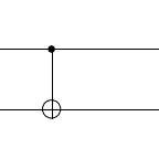
The CNOT gate leaves the control qubit unchanged but flips the target qubit if the control qubit is 1. Since the value of the control qubit determines whether a NOT gate is applied to the target qubit, the gate is called a controlled NOT gate or CNOT gate.
| Control (C) | Target (T) | Output (CNOT) |
|---|---|---|
| 0 | 0 | 0 |
| 0 | 1 | 1 |
| 1 | 0 | 0 |
| 1 | 1 | 1 |
The question concerned a 3-qubit gate called the Toffoli gate.
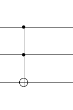
You can think of it either as a controlled CNOT gate, where the first qubit determines whether a CNOT is applied to the other two qubits. Alternatively as shown in the truth table below you can consider it a doubly controlled NOT gate where a NOT gate is applied to the last qubit only if both the first two qubits are 1.
| Control 1 (C1) | Control 2 (C2) | Target (T) | Output (Toffoli) |
|---|---|---|---|
| 0 | 0 | 0 | 0 |
| 0 | 0 | 1 | 1 |
| 0 | 1 | 0 | 0 |
| 0 | 1 | 1 | 1 |
| 1 | 0 | 0 | 0 |
| 1 | 0 | 1 | 1 |
| 1 | 1 | 0 | 1 |
| 1 | 1 | 1 | 0 |
The question
Let us now turn to the question. Here is a screenshot to illustrate the question format but there is no need to understand the details in order to follow the rest of the blog post. The only thing to note is that the problem asks you to construct a circuit.
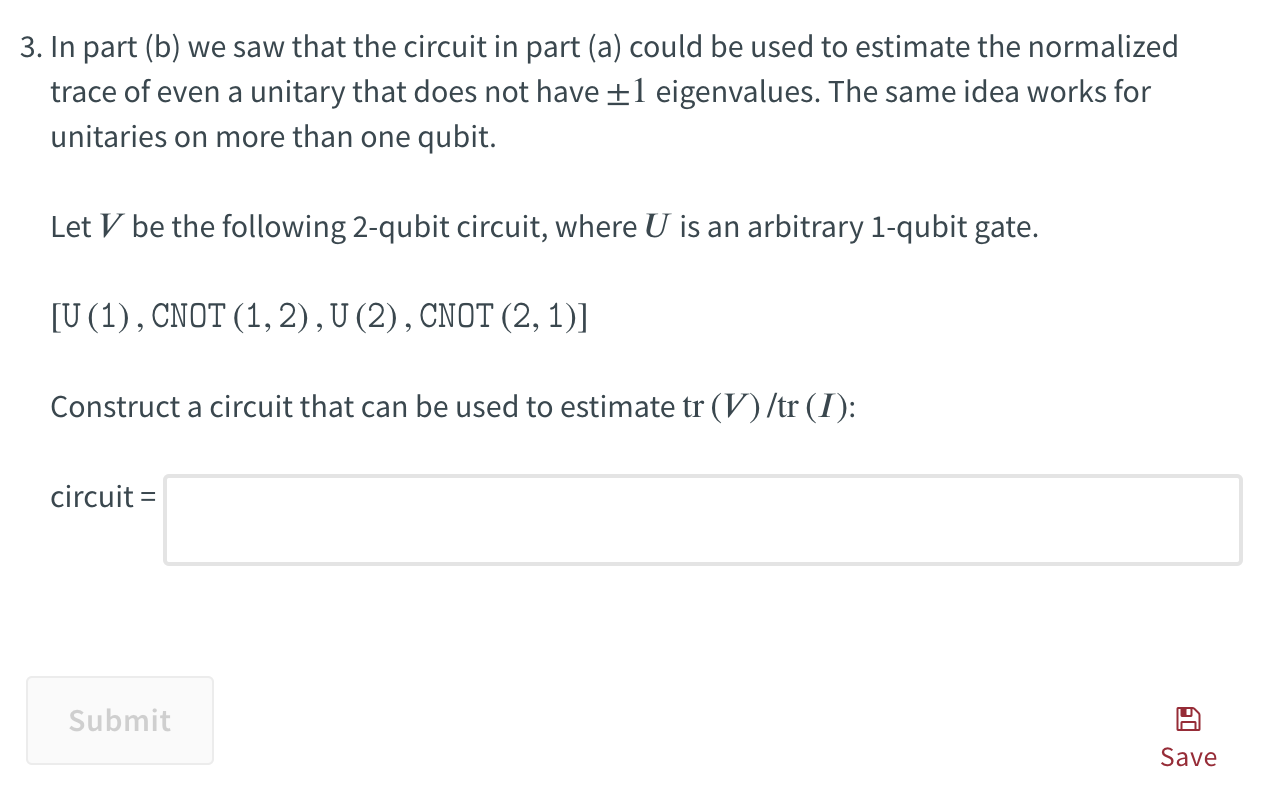
The answer needs to be input as a list of gates. Here is an example of the answer format:
[CNOT(0, 1),H(1),X(0)]
In case you are interested, here is an explanation of the gate format: X(0) means input the first qubit to the X gate (qubit numbering starts from 0), H(1) means input the second qubit to the H gate whilst CNOT(0, 1) means use the first qubit as the control input and the second qubit as the target input to the CNOT gate. The qubits are input into the gates in the list from left to right, first CNOT, then H and finally X.
The key takeaway is that the answer makes use of certain names for each gate. For example “H” stands for a gate called the Hadamard gate, “X” for the Pauli-X gate whilst the CNOT gate is simply input as “CNOT”.
The problem
At first sight the solution appeared to be straightforward. It involved a circuit made up of Toffoli gates and some other gates. Here is the diagram of the key part of the circuit:
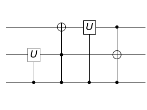
I now needed to input this in the required format of a list of gates. The issue arose when I could not figure out the right value to use to represent a Toffoli gate. The question did not provide any details about how to input the answer. I attempted different variants such as ‘Toff’, ‘T’, ‘TOFF’, ‘TOFFOLI’ and ‘toffoli’, none of which were permitted by the grader. It appeared that the Toffoli gate was not permitted in the answer and it seemed that the solution had be constructed using only 1-qubit or 2-qubit logic gates.
Maybe I ought to have sought guidance at this point but the MIT Open Learning Library, as the name implies, is a repository of course materials rather than a course provider so the platform lacks a forum or similar platform on which you can ask for help. I rarely use external forums like StackExchange or Reddit and had no wish to do so in this instance. So I decided to try to come up with a solution that only involved gates with 2 or fewer inputs.
Simplification
Always fascinated by the idea that something complex can be done in a simpler way, which is so important to the design of algorithms, I began to explore whether 3-qubit gates could be represented using 1-qubit and 2-qubit gates. In other words, can you feed the qubits, selecting at most 2 qubits at a time, through a sequence of 1-qubit and 2-qubit gates where the resulting output is equivalent to the output of a 3-qubit gate? I learned that it is indeed possible to implement a Toffoli gate using only 1-qubit and 2-qubit gates, as shown in the circuit below.

There is no need to understand the components of this circuit. It suffices to observe that each gate receives at most 2 inputs.
Returning to the problem, I replaced the Toffoli gate in my circuit with the 2-qubit version. However, as you can see, this circuit for the Toffoli gate involves a large number of gates. Indeed there are limits to the minimum size of this type of circuit. Annoyingly, the lengthy circuit appeared to cause issues with the grading system. I’m uncertain about the internal workings, but the testing mechanism appears to generate errors if the test execution takes too long. The grader failed altogether and was unable to inform me if the solution was correct or not.
So I started to wonder if there was an alternative approach.
Implicit computation
Another fascinating idea in computer science and mathematics is implicit computation, which involves finding ways to perform complex calculations without explicitly computing all the intermediate steps.
For example, imagine calculating the sum of all numbers from 1 to 100. Explicit computation would require adding each number one by one. However, as you may know, there is a well known mathematical formula for calculating the the sum of numbers from 1 to n which is n*(n + 1)/2. For n = 100, you can use the formula to obtain the result 100 * 101 / 2 = 5050 directly without individually adding all the numbers.
Thus far, I had assumed that because the circuit could be expressed in terms of Toffoli gates, you actually needed Toffoli gates to implement it. But was it, in fact, possible to arrive at the final output of the circuit without actually using Toffoli gates?
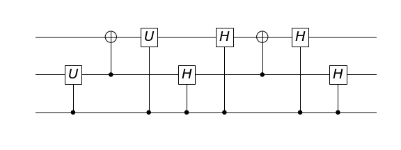
The answer is yes. The actual solution is quite technical and if you are interested in the details, I refer you to this blog post. But in a nutshell, you can build the particular circuit required for the solution without using Toffoli gates, relying solely on 2-qubit quantum gates. Below is a version of the key part of the solution which was shown earlier implemented using Toffoli gates but is here implemented using only 1-qubit and 2-qubit gates.
The “placebo effect”
Ironically I discovered that the grader did not expect any such solution. In fact it failed again when I input my new version. (Although I was able to verify independently that the solution was correct). One of the error messages that I got whilst playing around with the grader revealed the official solution which was simply the original straightforward solution that I had found at the start, involving Toffoli gates. Incidentally the correct way to input Toffoli gates turned out to be “Toffoli”.
That’s where the placebo effect comes in. In medicine, the placebo effect is a phenomenon in which a person experiences a perceived improvement in a condition or symptoms after receiving a treatment or intervention that has no therapeutic effect, solely due to a belief or expectation that it will work. Essentially, a belief without a real basis may lead to real benefits.
Likewise my false belief that the grader expected a solution satisfying certain requirements, namely a circuit built only using gates with a maximum of 2 inputs, led me to come up with a true solution. My efforts were fuelled by the assumption that since the grader expected it, such a solution must exist. But this proved to be a particularly useful mistake that led me on a learning journey during which I encountered interesting new ideas as well as seminal quantum computing papers that I might otherwise never have read.